
December 25, 2025 by Kenneth Wyatt
Collected at: https://www.eeworldonline.com/locate-esd-sources-using-an-oscilloscope-and-two-antennas/
The key to identifying the location of an ESD source is by measuring the time of arrival between the two antennas.
ESD discharges are tough to locate because they don’t occur periodically. Rather, they occur intermittently. I earlier wrote an application note on how to use an oscilloscope to trace the path of ESD current through your product [1]. In many cases, however, ESD discharges can result from various assembly or production areas in a large industrial facility. I once had to track down ESD events in a tire factory that were gradually degrading the batteries in an autonomous robotic system.
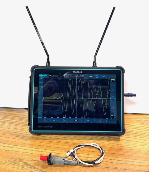
How can we use an oscilloscope to find ESD discharges in a factory environment? I first got this idea from Doug Smith [2] during one of his public seminars. The basic idea is to connect two short identical monopole antennas [3] to separate inputs on an oscilloscope (switch the inputs to 50 Ω impedance) and set the trigger for channel 1, Auto Trigger, and trigger on rise time. Adjust the trigger level for a stable capture by using a piezoelectric BBQ lighter, available in most hardware stores (burn off the gas, and you have a spark generator). Start with the horizontal set at 2 ns/division and the vertical at 200 mV/division.
A tablet oscilloscope, such as the Micsig TO3004 oscilloscope [4], is ideal for this application because all the input ports are along the top. That let me connect short telescoping antennas to channels 1 and 4 (for spacing). Figure 1 shows the oscilloscope with my BBQ lighter used as a test source.
Direction finding of ESD events
The ESD event results in a ring wave due to the inductive wire used as a transmitting “loop” antenna. The important part of the wave is the two leading edges of signals from channels 1 and 4. Note that as the wave ring decreases, the frequency also decreases; thus, for best accuracy, we want to set the cursors up near the start of the ringing.
Figure 2 shows the resulting waves with the ESD source off to the left side. The yellow trace (channel 1 and left-hand antenna in Figure 1) is the first one triggered, thus we see the left antenna received the wave first. Lagging behind by 560 ps is the green wave (channel 4 and right-hand antenna).
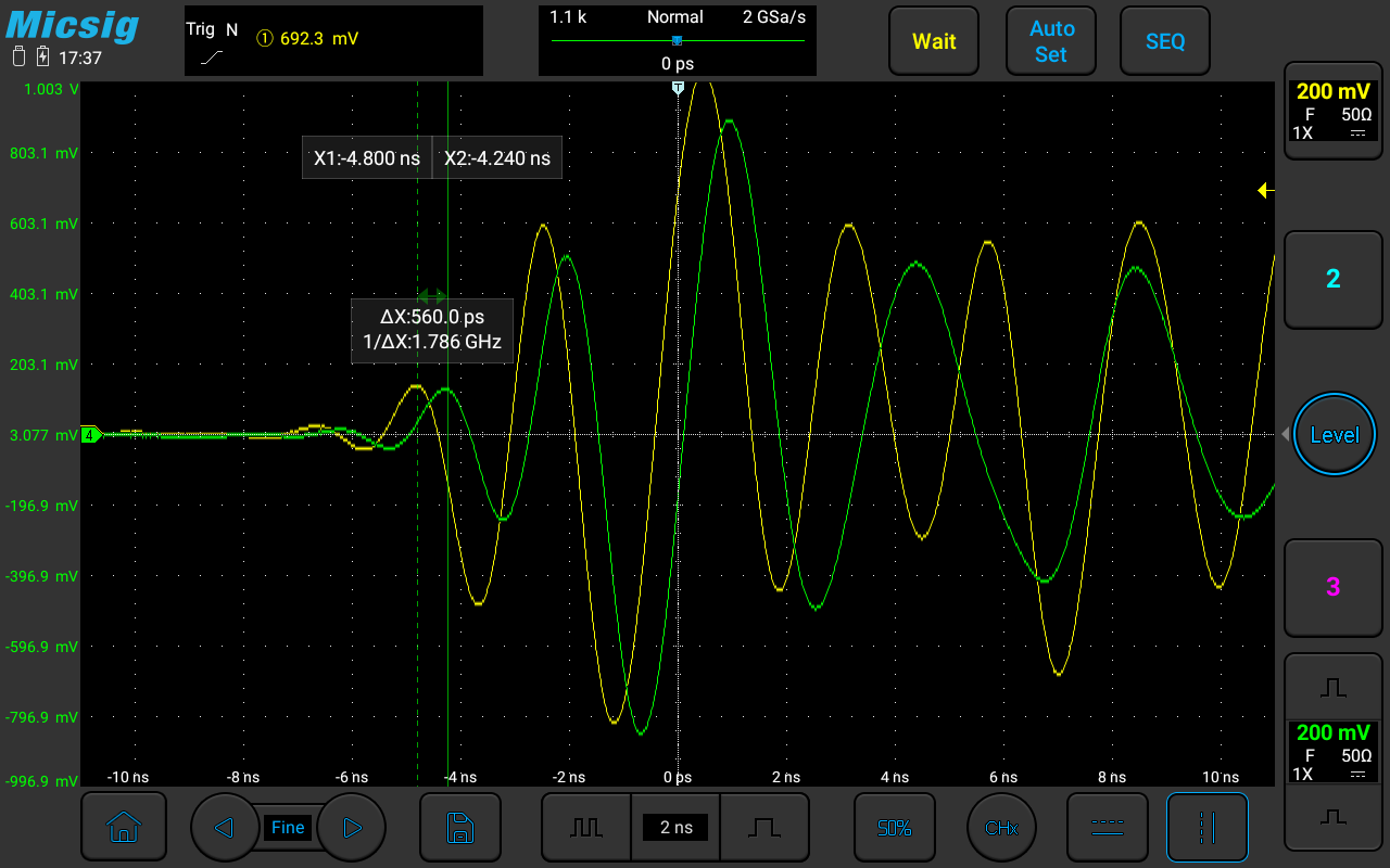
An interesting point is the “time-of-flight” calculation. This can be observed from the difference of 560 ps. Electromagnetic waves travel at about 12 inches per nanosecond in free space. The antennas are about 5.5 inches apart, so calculating the time-of-flight between the two antennas is equal to 5.5/12 = 0.4583 or 458 ps. This is in the ballpark of the 560 ps we measured using cursors.
Figure 3 shows the resulting waveforms with the ESD source straight on, facing the oscilloscope, and equidistant from each antenna. Here, we can see both wavefronts are coincident, indicating the ESD source is either straight ahead or directly behind the oscilloscope face and arriving at the antennas simultaneously.

Figure 4 shows the resulting waves with the ESD source off to the right side. The green trace (channel 4 and right-hand antenna) is the first one triggered, thus we see the right antenna received the wave first. Lagging behind by 520 ps is the yellow wave (channel 1 and left-hand antenna).

Because of the portability of the Micsig TO3004 and the fact that each antenna captures the ESD waves, simply lining up the wavefronts will either point you directly towards the ESD source or directly away from the source. By walking several feet one way or the other, you should be able to triangulate the source location.
One note. Because the antennas are relatively short and close together, there may not be sufficient signal capture. You may need to pull out the telescoping antennas further or increase the vertical amplitude sensitivity. I also find angling the two antennas away from each other helps separate the wavefronts a little more.
Another point is that by separating the antennas further apart, a greater difference in the time-of-flight separation in the two wavefronts may be recorded. For example, if the two antennas were connected to equal lengths of coax and handheld three feet apart, the wavefronts would be approximately 3 × 1 ns/foot = 3 ns difference, worst case.
Actual factory ESD example
Real-world ESD discharges will not generally look like nice, clean ring waves as produced by the BBQ lighter, but can look ugly (Figure 5). This was an example captured in that tire factory I mentioned earlier and consisted of multiple ESD bursts. While this may look complicated, remember that the important part of the wave is the front edge as captured by the oscilloscope. The differences in wavefronts will allow you to find direction just as in the examples above.

Summary
While any oscilloscope may be used to “direction find” the source of ESD discharge, a portable tablet oscilloscope like the Micsig TO3004 is ideal, because of the portability, plus with four inputs along the top, antennas may be placed apart from each other for the best directional angle resolution.
References
[1] Tektronix, Troubleshooting ESD failures using an oscilloscope
[2] Doug Smith
[3] Diamond RH789 antenna, Amazon
[4] Review: Micsig TO3004 tablet oscilloscope
Leave a Reply